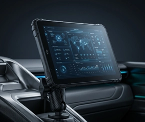
Vehicle Tablet Installation Checklist – 8 Steps for Fleet-Ready Deployment
A poorly installed tablet will fail — not because the hardware is bad, but because the installation cut corners. Whether you're deploying 5 tablets or 500, this checklist covers mounting, power, connectivity, and validation — the things that determine whether your fleet hardware works reliably from day one.
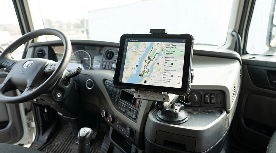
Table of Contents
Why Installation Is the Make-or-Break Step
A rugged tablet with IP67 rating and MIL-STD-810G certification can survive almost anything — except a bad installation. We've seen tablets fall off mounts because the bracket wasn't torqued properly. We've seen devices lose power mid-route because the wiring was spliced instead of using the proper vehicle harness. We've seen GPS signals drop because the antenna placement wasn't thought through.
These failures aren't hardware problems — they're deployment problems. And for system integrators and fleet managers deploying tablets at scale, the difference between a successful rollout and a support nightmare often comes down to whether a checklist was followed. That's why choosing rugged tablets designed for vehicle installation is only half the equation — the other half is proper installation discipline. Harden your fleet computing hardware →
"We deployed 50 tablets across our fleet last quarter. The first 10 went perfectly. By tablet #30, the installers got lazy — skipped the cable strain relief step on a few vehicles. Those exact units developed charging issues within 3 weeks. We learned the hard way: every single installation needs to follow the same checklist."
— Fleet deployment manager, logistics company
Step 1: Choose the Right Mounting Location
The mounting location determines everything else — driver visibility, cable routing, accessibility, and long-term stability.
Mount within the driver's line of sight but without obstructing the windshield — typically dashboard-level, slightly angled toward the driver
Avoid mounting directly above air vents — constant hot/cold cycling stresses electronics and loosens adhesive mounts
Ensure there's clearance for the tablet to dock and undock without hitting the steering wheel, gear shift, or other controls
For forklifts: overhead mounting on the ROPS cage is often preferred — use a RAM-compatible bracket rated for the vehicle's vibration profile
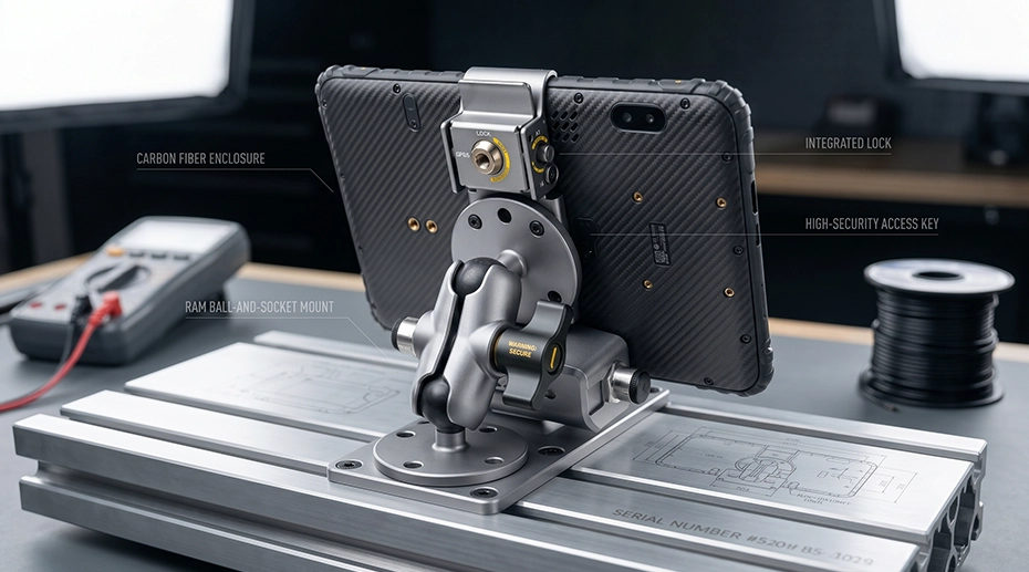
For deployments using vehicle mount terminals with dedicated docking stations, verify that the dock's locking mechanism engages fully at the chosen mounting angle — some RAM mount positions can prevent the latch from closing completely. Equip your fleet with secure vehicle mounts →
Step 2: Secure the Mounting Bracket Properly
A loose bracket means a loose tablet — and a loose tablet will eventually fall, disconnect, or rattle itself to death.
Use the hardware provided with the mount — don't substitute screws, bolts, or washers
Torque all fasteners to manufacturer specifications — under-torquing leads to vibration loosening; over-torquing can strip threads or crack mounting surfaces
Apply thread-locking compound (Loctite Blue or equivalent) on all metal-to-metal fasteners in high-vibration environments
For adhesive mounts: clean the surface thoroughly with isopropyl alcohol, apply even pressure during curing, and wait the full cure time before attaching the tablet
After installation, grab the bracket and try to shake it — there should be zero movement. If it moves at all, re-torque or reinforce before proceeding.
Step 3: Route and Protect All Cables
Cable failure is the #1 cause of post-installation problems. A cable that's pinched, stretched, or rubbing against a metal edge will fail — usually at the worst possible time.
Route all cables away from moving parts — steering columns, pedals, seat adjustment mechanisms, and door hinges
Use cable ties or clips every 15-20 cm to prevent sagging and vibration wear
Anywhere a cable passes through a metal panel or bulkhead: use a rubber grommet. No exceptions — a cut cable from a sharp metal edge is not covered by warranty.
Leave a small service loop (5-8 cm of slack) at the tablet connection point — this absorbs vibration and allows the tablet to be undocked without straining the connector
Label both ends of every cable. When troubleshooting 6 months later, you'll thank yourself.
Step 4: Connect Vehicle Power Safely
This is the step where shortcuts cause real damage — to the tablet, to the vehicle, or to both. In professional fleet management tablet operations, power stability is paramount. Always refer to the official System Topology & Wiring Diagram (Figure 1) below when running your cables. Configure a professional vehicle power setup →
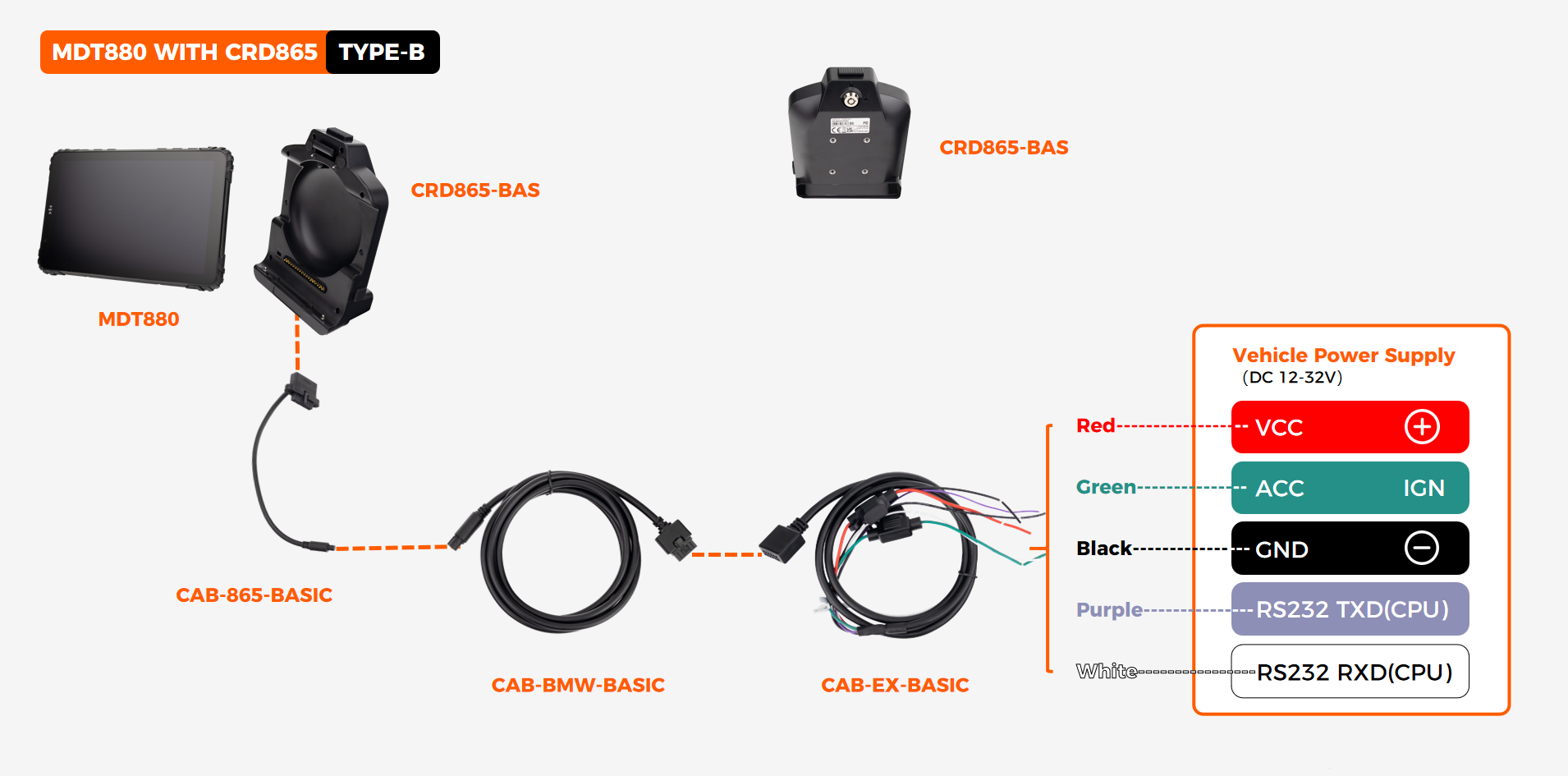
Figure 1: Complete 3-wire installation layout using CAB-865-BASIC, CAB-BMW-BASIC, and CAB-EX-BASIC cabling system.
Mandatory Wiring Requirements
As detailed in the technical diagram above, a standard enterprise deployment requires strict adherence to the following 3-wire power configuration:
VCC (Red – Constant Power): Connect directly to a fused circuit or install an in-line fuse (typically 5A) to provide continuous power.
ACC/IGN (Green – Ignition Sense): Connect to a circuit hot only when the engine is running. Enables automatic power on/off with the vehicle, preventing battery drain.
GND (Black – Ground): Connect directly to a clean, unpainted metal surface on the vehicle chassis — do not splice into an existing ground wire shared with high-load electronics.
Peripheral Integration (Purple/White): Integrated RS232 TXD/RXD lines broken out from the same harness for secure data communication with external sensors or ELD peripherals.
OEM Engineering Note for 24V Fleet Vehicles: Verify the tablet's voltage tolerance before deployment. All TOPICON MDTs natively support DC 12-32V (up to 36V depending on spec), eliminating the need for external voltage converters. For ELD compliance, get a dedicated ELD-ready power harness →
Core Installation Rules
Never Use Electrical Tape: Use the professional vehicle power harness designed for the tablet. Splicing creates unreliable connections under vibration and voids the hardware warranty.
The Multimeter Test: Before docking the tablet, test the terminal connector with a multimeter. Verify stable 12V/24V, correct polarity, and that the ignition sense wire switches accurately with the key.
Step 5: Position External Antennas for Best Signal
If your deployment uses external GPS or cellular antennas, placement makes the difference between reliable tracking and constant signal dropouts. For vehicle mount tablets with external antenna support, correct placement is critical.
GPS antennas need a clear view of the sky — mount on the dashboard (inside, near windshield) or on the vehicle roof (external, magnetic or screw-mount)
Keep GPS antennas at least 30 cm away from metal obstructions, roof racks, and other antennas
Cellular antennas work best when mounted high on the vehicle — roof-mount provides the best coverage in rural areas
Test GPS and cellular signal strength with the tablet powered on before finalizing cable routing
Step 6: Dock the Tablet and Verify the Connection
The physical installation is done — now verify that everything works before moving on to software configuration.
Dock the tablet — listen for an audible click or confirm the locking mechanism is fully engaged
Verify the tablet shows "charging" or "connected to dock" on screen
Gently pull on the tablet — it should not move or disconnect
Test undocking and re-docking 3 times — the mechanism should operate smoothly each time
Start the vehicle engine — confirm the tablet powers on automatically (ignition sense working). For a factory-grade vehicle data terminal deployment, this ignition‑triggered power sequence is non‑negotiable.
Step 7: Configure Software and Test Connectivity
Hardware is working — now make sure the software and network connections are solid. For fleets deploying transportation tablets, verifying that dispatch, navigation, and ELD apps all function correctly before the vehicle leaves the yard is essential. Set up your fleet communication hub →
Confirm the tablet is enrolled in your MDM platform and receiving the correct configuration profile
Verify all required fleet apps are installed and launch correctly — ELD, navigation, dispatch, inspection apps
Test GPS lock: open a mapping app and confirm the tablet shows an accurate location within 30 seconds
Test cellular data: load a web page or ping your fleet server — confirm connectivity in the actual vehicle location
If using CAN Bus integration: verify engine data (RPM, fuel, fault codes) is being captured by the fleet software
Step 8: Document and Log the Installation
Documentation is the difference between a professional deployment and an amateur one. When something goes wrong 6 months later, you need to know exactly what was installed, where, and how.
Record the vehicle ID, tablet serial number, and installation date in your asset management system
Take a photo of the completed installation — dashboard view showing tablet placement and cable routing
Note any deviations from the standard installation procedure
Log the firmware version, OS version, and installed app versions at the time of deployment
File the installation record — this becomes your baseline for troubleshooting, warranty claims, and future upgrade planning
Quick Reference: Pre-Deployment Validation Checklist
Common Installation Mistakes That Cause Field Failures
✕ Splicing into Existing Wiring
Creates unreliable connections that fail intermittently. Always use the proper vehicle power harness.
✕ Skipping the Ignition Sense Wire
Without ignition sensing, the tablet stays on 24/7 — draining the vehicle battery overnight.
✕ No Cable Strain Relief
A cable hanging from the tablet puts constant tension on the connector, causing intermittent charging failures.
✕ Mounting Without Testing the Position
A mount that looks right in the workshop may block the driver's view or interfere with controls.
Frequently Asked Questions
How long does a typical vehicle tablet installation take?
A standard installation by an experienced technician takes 45-90 minutes per vehicle. First-time installations may take 2+ hours. Complex setups with CAN Bus integration, external antennas, and multi-camera systems can take 2-3 hours.
Can I install fleet tablets myself, or should I hire a professional?
Basic installations (dashboard mount + 12V power) can be done by in-house maintenance staff following this checklist. For installations involving CAN Bus integration, 24V heavy equipment, or multi-camera systems, professional installation is recommended. Contact us for installation support →
What's the most common reason for post-installation tablet failures?
By far, cable-related issues — loose connectors from missing strain relief, pinched cables causing intermittent shorts, and poor wiring splices that corrode over time. Following the cable routing and power connection steps in this checklist prevents the vast majority of field failures.
How many spare tablets should I keep for a fleet deployment?
For deployments of 50+ vehicles, keep 5-10% spare units configured and ready to deploy. For smaller fleets, 1-2 spare units are sufficient. Spares should be pre-enrolled in MDM with all fleet apps installed so they can be swapped in within minutes, not hours.
Deploying Fleet Tablets? Start with Hardware Built for Vehicle Installation
TOPICON rugged MDTs come with vehicle-grade power harnesses, locking docking stations, and comprehensive installation support — purpose-built for fleet deployment at scale.
Related Deployment & Fleet Hardware Resources