CAN Bus vs OBD-II for Fleet Tablets — Data Depth, Wiring, and Diagnostic Architecture
A fleet integration team installs a tablet with an OBD-II adapter and expects to read brake status, transmission gear, and PTO engagement. The adapter connects, the app launches, and the data stream shows engine RPM and coolant temperature — nothing more. The team replaces the adapter. The result is identical. The problem is not the adapter. The problem is that OBD-II was never designed to expose those data. This article explains what each protocol reads, how the wiring differs, and how the choice affects tablet hardware selection.
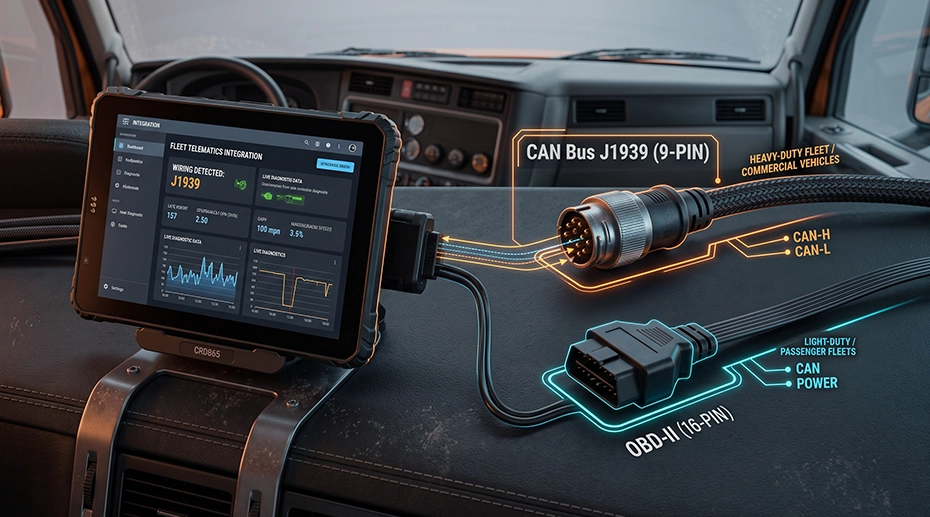
Table of Contents
1. The Integration Scenario
A telematics software vendor builds a fleet monitoring platform that displays engine data, vehicle location, and driver behaviour. The first pilot deployment uses a consumer OBD-II adapter plugged into the diagnostic port under the dashboard. The adapter reads standard PIDs — engine RPM, vehicle speed, coolant temperature, intake manifold pressure. The platform works as designed for those signals.
The second phase of the rollout requires brake status, transmission gear position, PTO engagement, and axle load. The OBD-II adapter returns none of these. The vendor adds a second adapter. Still nothing. The diagnostic port does not carry those signals, and no adapter can extract what is not on the bus.
The integration team then discovers that the fleet's vehicles carry a J1939 CAN Bus network that does expose those signals — but it is wired to a different connector behind the dashboard, not to the OBD-II port. The OBD-II port carries only emissions-related PIDs; no adapter can extract J1939 signals from it. The hardware solution is a tablet with a native CAN Bus interface that supports both protocols. The MDT series reads OBD-II and J1939 through the same interface, with the protocol selected in firmware. This removes the external adapter from the failure path.
2. What OBD-II Was Designed For
OBD-II is an emissions diagnostic standard. It was mandated in the United States in 1996 and adopted in Europe as EOBD. Its purpose is to give a service technician access to emissions-related fault codes and live data from the engine control unit. It was never intended as a vehicle data bus for third-party applications.
The standard defines a physical connector (J1962), a set of diagnostic services, and a list of standard PIDs. The PIDs cover engine-related parameters: RPM, coolant temperature, intake air temperature, throttle position, oxygen sensor readings, and diagnostic trouble codes. Vehicle speed is included because it is used by the emissions control logic.
What OBD-II does not carry: brake pressure, transmission gear selection, PTO status, axle load, body control data, or any signal outside the powertrain emissions scope. These signals exist on the vehicle, but they are not exposed through the diagnostic port. For fleet operations that need this data, OBD-II is the wrong interface — not because the adapter is insufficient, but because the protocol does not include the signals.
3. What CAN Bus J1939 Adds
J1939 is the SAE standard for heavy-duty vehicle networks. It runs on the CAN Bus physical layer — the same twisted-pair differential wiring used in automotive and industrial networks — but defines a different message structure. Where OBD-II uses 11-bit identifiers and a fixed PID list, J1939 uses 29-bit identifiers and a parameter group numbering system that covers the entire vehicle, not just the powertrain.
• Transmission data: Current gear, selected gear, torque converter lockup, oil temperature
• Brake data: Brake pedal position, brake pressure, ABS status, retarder status
• Body and auxiliary data: PTO engagement, cab status, door position, hydraulic pressure
• Vehicle dynamics: Wheel speed per axle, suspension load, steering angle
The same CAN Bus physical layer carries both OBD-II and J1939 in many commercial vehicles. They differ in identifier length, data rate, and message content. A tablet with a dual-CAN interface can read both simultaneously, but the wiring and connector access differ — which brings us to the installation.
4. Wiring and Electrical Differences
OBD-II is accessed through the J1962 connector under the dashboard. Power comes from the vehicle through pins 16 (battery positive) and 4/5 (ground). The adapter is typically powered from this connector and communicates over the CAN Bus pins (6 and 14 for ISO 15765-4 CAN).
J1939 is accessed through a 9-pin Deutsch connector or a 3-pin diagnostic connector, depending on the vehicle. The network itself is a twisted-pair bus with 120-ohm termination resistors at each end. CAN H and CAN L carry the differential signal. The bus runs at 250 kbps or 500 kbps depending on the vehicle.
Two electrical details matter for tablet integration. First, the ground reference. The tablet is mounted on the dashboard or console; the CAN Bus is wired through the vehicle chassis. If the tablet ground and the chassis ground differ by even a few hundred millivolts, the differential signal can shift outside the receiver's common-mode range. A ground loop diagnosis guide covers the physical mechanism and the troubleshooting procedure.
Second, the ignition state. A tablet powered from the OBD-II port stays powered after the key is removed unless something tells it otherwise. A J1939 connection typically includes an ignition sense line. The tablet follows the vehicle state — power on at key-on, controlled shutdown at key-off. This prevents the tablet from draining the battery overnight, which is a common failure in fleets that use OBD-II adapters without ignition sensing.
TOPICON MDT880 / MDT865 Vehicle Docking Guide: RAM Mount, Wiring Harness & Key Lock Demo
Step-by-step demonstration of vehicle docking installation, including 9–36V wiring harness and key lock mechanism for CAN Bus integration.
5. How This Changes Tablet Selection
The protocol decision determines the hardware interface. A tablet with a native CAN Bus interface connects directly to the vehicle network. The MDT series supports J1939, OBD-II, and proprietary CAN protocols through the same hardware interface — no external adapter between the vehicle and the application. The protocol is selected in firmware, not by swapping hardware.
Three specifications determine whether the tablet can serve the deployment.
• Isolation: An isolated CAN interface breaks the ground loop between the tablet and the vehicle chassis. This prevents data corruption and protects the transceiver from voltage transients during engine cranking and load switching.
• 29-bit identifier support: J1939 uses 29-bit extended identifiers. A tablet whose CAN controller supports only 11-bit standard identifiers cannot read J1939 frames. This is a specification that must be verified, not assumed.
The CAN Bus vehicle tablet platform documentation covers the channel count, isolation, and identifier support for the MDT series. A tablet like the MDT865 provides dual CAN channels with J1939 support, RS232, RS485, GPIO, and RJ45 — covering the full interface set required by a telematics integration.
6. Deployment Checklist
Before specifying tablet hardware for a CAN Bus or OBD-II integration, confirm the following on the target vehicle:
• Connector: Is there a 9-pin Deutsch, a J1962 OBD-II port, or a manufacturer-specific diagnostic connector?
• Termination: Are the 120-ohm termination resistors present at both ends of the CAN Bus? Missing termination causes reflections and data loss.
• Data rate: Is the bus running at 250 kbps or 500 kbps? The tablet's CAN controller must be configured to match.
• Ground reference: Is the tablet ground bonded to the vehicle chassis at the same point as the CAN Bus ground?
• Ignition state: Is there an ignition sense line available for the tablet power input, or does the tablet need a switched supply from the distribution panel?
• MDM diagnostics: Can the MDM platform remotely read the CAN Bus status and log errors, or does a technician need to visit the vehicle?
The docking station matrix maps each tablet model to the CAN-capable docks and the wiring harness options. The CAN Bus integration guide for system integrators covers the software-side configuration.
Single Point of Failure
A fleet tablet that cannot read the vehicle network is not a data collection platform — it is a display. The application layer depends entirely on the CAN Bus interface underneath it. If the interface is an external OBD-II adapter, that adapter becomes a single point of failure: one loose connection, one thermal fault, one ground offset, and the entire telematics platform stops receiving vehicle data. A native CAN interface inside the tablet removes that failure point. The protocol decision — OBD-II or J1939, single-channel or dual-channel, isolated or non-isolated — determines whether the tablet is a data collection device or a screen that shows an app. The hardware selection follows the protocol requirement, not the other way around.
7. Frequently Asked Questions
Can a fleet tablet read both OBD-II and J1939?
Yes, if the tablet has two CAN channels or a switchable adapter. OBD-II uses 11-bit identifiers and standard PIDs. J1939 uses 29-bit identifiers and PGNs. The two protocols can share the same physical layer but not the same message format. A dual-CAN tablet can read engine data from OBD-II and brake or transmission data from J1939 at the same time. The CAN Bus tablet platform documentation covers the channel configuration.
Does OBD-II provide brake and transmission data?
OBD-II was designed for emissions diagnostics. It exposes engine-related PIDs such as RPM, coolant temperature, and fault codes. Brake, transmission, PTO, and body data are generally not available through standard OBD-II. Those signals live on J1939 or proprietary CAN networks. No OBD-II adapter can extract signals that the protocol does not carry.
What causes CAN Bus data corruption in vehicles?
Common causes include missing or incorrect terminal resistors, ground loops between the tablet and the vehicle chassis, long stub lines, and unshielded wiring near ignition or alternator cables. A ground loop can shift the differential voltage enough that CAN H and CAN L no longer cross correctly, producing random or missing frames. The ground loop diagnosis guide covers the physical mechanism and the troubleshooting procedure.
How do I read OBD-II and J1939 simultaneously if the vehicle has two separate CAN buses?
The tablet reads OBD-II and J1939 through its CAN interface, with the protocol configured in firmware. If the vehicle carries OBD-II and J1939 on two independent CAN networks, you need two CAN channels. This can be done in two ways: specify a dock harness that exposes two CAN channels, or add the EXT-USB-CAN-01 adapter, which converts the tablet's USB-A (OTG) port into two additional CAN channels. The native CAN interface and the USB-CAN adapter can operate at the same time, giving the tablet access to two separate vehicle networks.
How is CAN Bus data accessed remotely for fleet diagnostics?
The tablet's CAN interface feeds data to the application, which can log it locally or forward it to a backend platform. The TOPICON MDM platform provides remote access to device logs and system status, so an administrator can check whether the CAN interface is active without visiting the vehicle. For remote ADB and screen control — useful when diagnosing why a CAN interface stopped reporting — the MDM platform provides browser-based access to the device. CAN protocol configuration (J1939, OBD-II, or proprietary) and channel assignment can also be checked and adjusted remotely without a vehicle visit.
Integrating CAN Bus Data into a Fleet Platform?
The protocol requirement — OBD-II, J1939, or both — determines the tablet interface and the wiring architecture. Request a hardware evaluation kit or discuss the CAN Bus configuration for your fleet deployment.
Related CAN Bus & Fleet Integration Resources