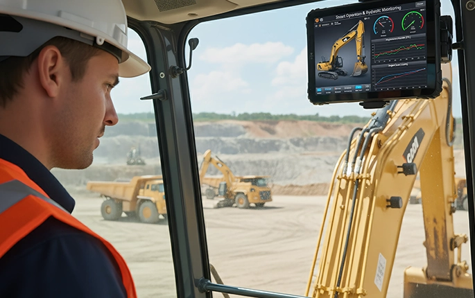
CAN Bus Integration for Fleet Tablets – What System Integrators Need to Know Before Deployment
CAN Bus integration looks straightforward on paper: connect two wires, configure the baud rate, start reading data. But when you're deploying across a mixed fleet of trucks, buses, and heavy equipment — each with different CAN architectures, different electrical systems, and different data rate requirements — the integration layer becomes the hardest part of the project. Here's what to plan for before you start wiring.
Why CAN Bus Integration Fails in Fleet Projects
Most CAN Bus integration problems aren't protocol problems. They're planning problems. A system integrator configures everything correctly on the bench — correct baud rate, correct message IDs, correct signal definitions — and it works perfectly with the test ECU. Then the tablets get installed in 50 vehicles, and suddenly: intermittent data dropouts. Missing engine hours. RPM values that freeze for 5 seconds then jump. ELD log gaps that correlate with CAN bus errors nobody can reproduce in the workshop.
The root cause is rarely the CAN controller or the tablet. It's the deployment planning — or lack of it — around the electrical environment, the vehicle's existing CAN network topology, and the data bandwidth limits that nobody calculated before installation. For system integrators deploying industrial rugged tablets with CAN Bus interfaces, understanding these six technical areas before the first vehicle is wired is what separates a smooth rollout from a support nightmare.
"We integrated CAN Bus on 30 trucks. Worked perfectly on the first 5 — all same model, same year. Truck #6 was a different model year with a different ECU gateway. The CAN IDs we'd mapped didn't match. We had to re-map the entire signal database. Took 2 weeks we hadn't budgeted for."
— Systems engineer, telematics integration company
Six Technical Areas to Plan Before Deployment
1. CAN Protocol Selection: J1939 vs CAN 2.0B vs CAN FD
Not all CAN networks speak the same language. Selecting the wrong protocol layer means your tablet can't interpret the data coming from the vehicle — even if the electrical connection is correct.
Planning action: Before specifying hardware, document every vehicle make, model, and model year in the deployment fleet. Different model years of the same truck can have different CAN architectures. The integration that works on a 2023 Peterbilt 579 may fail on a 2020 model — same truck, different ECU gateway.
2. Electrical Compatibility: Voltage Levels, Termination, and Grounding
CAN Bus is electrically robust by design — differential signaling with error detection and fault confinement. But those protections only work when the electrical installation is correct. Three things cause the majority of fleet-wide CAN problems.
Termination resistors: A CAN bus requires exactly two 120Ω termination resistors — one at each end of the bus. Adding a third device with its own termination creates impedance mismatch and signal reflection. Removing both terminators causes the bus to float. Either condition produces intermittent errors that are extremely difficult to diagnose because they depend on bus load, temperature, and cable routing.
Ground offset between vehicle and tablet: CAN differential signaling tolerates some ground offset, but if the tablet's power ground and the vehicle's CAN ground differ by more than a few volts, the common-mode voltage exceeds the transceiver's range. This typically happens when the tablet is powered from a different circuit than the CAN interface — use a common ground point for both power and CAN.
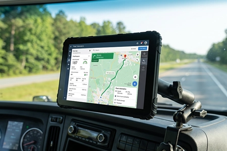
24V vehicle systems: Heavy trucks, buses, and construction equipment use 24V electrical systems. The CAN bus voltage levels are the same regardless of vehicle voltage — CAN_H and CAN_L are referenced to the transceiver's supply, not the vehicle's battery. But the tablet's power input must handle 24V. All TOPICON MDTs support 9-36V DC input, covering both 12V and 24V systems without converters.
3. Dual CAN Architecture: When One Channel Isn't Enough
A single CAN interface can read data from one bus — typically the vehicle's powertrain CAN. But modern fleet applications increasingly need access to two separate CAN networks simultaneously.
Scenario A: Powertrain + Body CAN
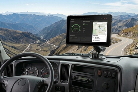
The powertrain CAN carries engine data (RPM, fuel, fault codes). The body CAN carries door status, lighting, HVAC, and driver controls. A telematics platform that monitors both engine health and driver behavior needs both buses — simultaneously. Reading one, then the other, means missing events on the idle bus.
Scenario B: Vehicle CAN + Aftermarket Sensor CAN
The tablet reads vehicle data from the OEM CAN bus while simultaneously communicating with aftermarket sensors — weight scales, temperature probes, tire pressure monitors — on a separate CAN network. This keeps aftermarket traffic off the vehicle's mission-critical bus.
Planning action: Specify a tablet with dual CAN controllers — not a single controller with a multiplexer. Dual independent controllers allow different baud rates on each channel (e.g., 500 kbps on J1939 powertrain, 250 kbps on body CAN) and simultaneous operation without channel switching latency. Explore dual CAN Bus rugged tablets →
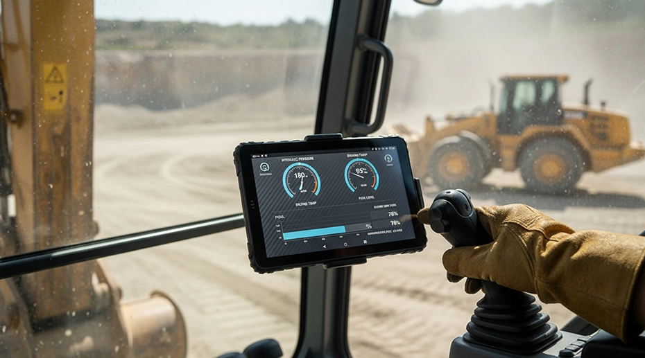
4. Data Bandwidth Planning: How Much CAN Data Is Too Much?
A J1939 bus at 250 kbps can carry roughly 1,500-2,000 messages per second — but that's the theoretical maximum of the transport layer, not a number you should plan to consume. In practice, a heavily loaded vehicle CAN bus is already at 40-60% utilization before your tablet connects. Your application needs to be selective about what it reads.
Bandwidth Planning Checklist
Identify critical PGs first: For ELD compliance, you need EEC1 (engine speed), CCVS (vehicle speed), LFC (fuel consumption), and DM1 (active fault codes). These are mandatory. Everything else is optional — add only after verifying the bus can handle the additional traffic.
Calculate your polling rate needs: ELD requires engine data at 1 Hz (once per second). Driver behavior analysis may need 10 Hz. Don't request data faster than you need it — each request consumes bus bandwidth.
Watch for the J1939 transport protocol bottleneck: Multi-frame messages (more than 8 bytes) require the transport protocol to reassemble frames. If your tablet is processing multiple multi-frame messages simultaneously, the reassembly buffer can overflow — silently dropping data. Test this on a real vehicle under load, not just on the bench.
Log CAN bus load during integration testing: Use a CAN analyzer to measure actual bus utilization during your test drives. If utilization exceeds 70%, your application is contributing to bus congestion — reduce your polling rate or remove non-critical PGs.
5. Time Synchronization: Why CAN Data and GPS Time Must Agree
ELD regulations require HOS records to be time-stamped accurately. FMCSA mandates that ELD time must be synchronized to UTC within 10 minutes. But there's a subtlety most integrators miss: the CAN data coming from the vehicle has its own time domain, and the GPS time on the tablet is another. If these clocks drift apart, you can get situations where the GPS timestamp says the vehicle was moving, but the CAN data timestamp says the engine was off — a compliance discrepancy that's hard to explain during an audit.
The solution is timestamp reconciliation at the application layer: tag every CAN message with the GPS-derived UTC timestamp at the moment it's received by the tablet — not the moment it was transmitted by the ECU. This accounts for CAN bus latency, message queuing delays, and any clock drift between the vehicle's ECU and the tablet's GNSS receiver. The ELD application should use the GPS timestamp for HOS records, not the ECU timestamp.
6. Validation Testing: What to Test Before Fleet Rollout
Bench testing with a simulated ECU is necessary but insufficient. A CAN bus analyzer connected to a test ECU generates clean, predictable traffic — real vehicle buses are noisy, contested, and sometimes carry malformed messages from faulty sensors. Your integration needs to survive the real electrical environment. For deployments using fleet management tablets with CAN Bus integration, real-vehicle validation across multiple vehicle variants is not optional.
Pre-Deployment CAN Validation Checklist
Test on at least 3 vehicles of different model years from the target fleet — ideally one older vehicle with higher bus noise
Monitor CAN error frames during a full driving cycle — any error rate above 0.1% indicates an electrical issue (grounding, termination, or cable routing)
Test cold-start CAN behavior: some ECUs take 2-5 seconds after ignition to begin transmitting. Your application must handle the initialization delay gracefully — not report it as a CAN failure
Test with engine off, ignition on: many fleet workflows involve paperwork or inspections while parked. The CAN bus may still be active but carrying different traffic patterns
Run a 48-hour continuous logging test on at least one vehicle — check for memory leaks, buffer overflows, or timestamp drift that only appear after extended operation
Pre-Deployment CAN Bus Integration Checklist
Frequently Asked Questions
What's the most common CAN Bus integration mistake on fleet deployments?
Assuming all vehicles of the same model have the same CAN architecture. Different model years can have different ECU gateways, different CAN IDs, and different signal mappings — even within the same truck model. Always test on the specific vehicles being deployed, not just a representative sample.
Do I need dual CAN channels, or is a single channel enough?
If your application only needs engine data for ELD compliance, a single CAN channel reading the powertrain bus is sufficient. If you also need body CAN data (door status, driver controls, HVAC), aftermarket sensor integration, or simultaneous J1939 and CAN 2.0B support, dual independent CAN controllers are required. Explore dual CAN Bus tablets →
How do I get the DBC file or CAN signal definitions for a vehicle?
For heavy-duty trucks using J1939, the standard parameter group definitions are publicly documented — no OEM-specific files needed. For light-duty vehicles using CAN 2.0B with OEM-specific messaging, access to the DBC file typically requires a relationship with the vehicle manufacturer or a third-party database provider. Plan for this during the procurement phase, not after vehicles are delivered.
Does TOPICON provide CAN Bus integration support for system integrators?
Yes. TOPICON provides CAN Bus SDK and API documentation, dual CAN hardware platforms with J1939 and CAN 2.0B support, and engineering consultation for system integrators planning fleet-wide CAN deployments. Contact our integration engineering team →
Planning CAN Bus Integration for Your Fleet Project?
TOPICON provides dual CAN Bus rugged tablets with J1939 and CAN 2.0B support, SDK/API documentation, and engineering consultation for system integrators.
Related Integration & Deployment Resources