How Vehicle Ground Loops Corrupt CAN Bus Data – Causes, Diagnosis & Hardware Solutions
Fleet telematics data shows erratic RPM readings, intermittent fault codes, and CAN Bus error frames that come and go. The engine isn't the problem. The wiring isn't faulty. A ground loop is injecting electrical noise into the vehicle data network — and most fleet hardware isn't built to handle it.
Table of Contents
The Problem: When CAN Bus Data Makes No Sense
A fleet operator reports intermittent telematics anomalies. Engine RPM readings spike by 500-600 RPM for fractions of a second, then return to normal. Fuel consumption data shows gaps — entire minutes where no data was recorded. Fault codes appear for sensors that pass every bench test. The data looks corrupted, but only sometimes.
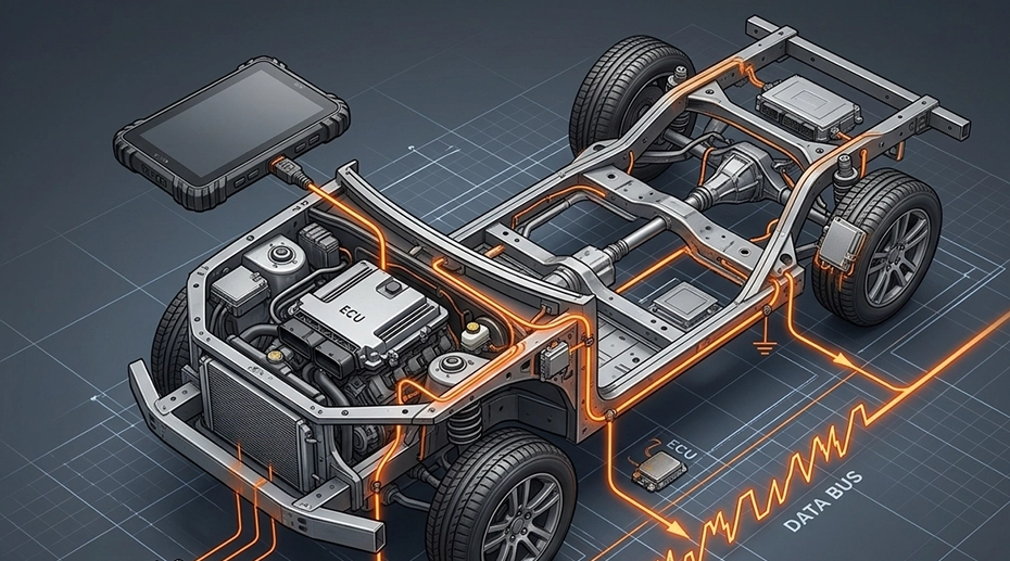
This pattern is consistent across a specific subset of vehicles — heavy-duty trucks, mining equipment, and construction machinery with multiple ECUs, high-current electrical systems, and complex chassis grounding architectures. It does not appear in passenger vehicles or light commercial vans.
The root cause is not a faulty ECU. It is not a loose connector or a failing sensor. It is a ground loop — an unintended current path through the vehicle chassis that couples electrical noise directly onto the CAN Bus data lines. And most fleet telematics hardware, including many rugged tablets, provides no protection against it.
Key takeaway: CAN Bus is a differential protocol designed to reject common-mode noise. But differential signaling has limits. A ground loop that introduces enough potential difference between the MDT and the vehicle chassis overcomes those limits — and the CAN controller sees corrupted data.
What Is a Ground Loop — The Physics
A ground loop occurs when two points in a circuit that should be at the same potential are instead at different potentials — creating an unintended current path.
How It Forms in Vehicles
A truck has multiple ground points — the engine block, the chassis rail, the cabin floor, the dashboard frame. When high-current devices (starter motor, alternator, hydraulic pumps, refrigeration units) draw power, they create voltage drops across these ground paths. Two ground points that should be at 0V can differ by several volts during load transients. If the MDT is grounded at one point and the CAN Bus transceiver references a different point, that voltage difference appears as noise on the data lines.
Why Heavy Vehicles Are More Vulnerable
Heavy-duty trucks, mining equipment, and construction machinery use 24V electrical systems with higher current draws than passenger vehicles. Their chassis are larger, with longer ground return paths and more ground points. They often run auxiliary equipment (PTOs, hydraulic pumps, crane motors) that create large transient currents. And they operate in environments — mud, water, dust — that degrade ground connections over time, increasing resistance at contact points and making potential differences larger.
Symptoms of CAN Bus Data Corruption from Ground Loops
These six symptoms appear specifically when ground loop noise couples onto the CAN Bus — and they have a characteristic pattern.
Intermittent Data Dropouts
CAN Bus data stops for seconds or minutes, then resumes without intervention. Dropouts correlate with electrical load changes — when the alternator kicks in, when hydraulic pumps activate, when the refrigeration unit cycles on.
Spurious Fault Codes
DTCs appear for sensors that pass bench testing. The fault codes are not reproducible when the vehicle is stationary. They occur only during operation — when electrical noise is present on the bus.
Erratic Sensor Readings
RPM jumps by hundreds for single samples. Fuel rate shows impossible values. Coolant temperature spikes that do not match physical reality. These single-sample glitches are classic noise artifacts.
CAN Error Frame Counter Increasing
The CAN controller logs error frames — CRC errors, bit errors, form errors. The error counter increments over time but resets when the MDT is powered from an isolated supply. This is a strong diagnostic signal.
Correlated with Vehicle Operations
Corruption occurs when specific electrical loads activate — the starter cranking, the alternator charging at high output, the PTO engaging. The timing is not random; it follows the vehicle's electrical load profile.
Disappears with Battery-Only Power
When the MDT is disconnected from vehicle power and runs on its internal battery, CAN Bus data corruption stops. This is the definitive diagnostic test — it isolates the vehicle electrical system as the noise source.
How to Diagnose a Ground Loop in Vehicle Installations
Three steps to isolate the root cause — from quick check to definitive measurement
Measure Chassis Ground Potential Difference
Use a multimeter to measure AC and DC voltage between the MDT's ground connection point and the CAN Bus shield ground point. With the engine running and electrical loads cycling, any reading above 50mV AC or 100mV DC indicates a problematic potential difference. In heavy vehicles with 24V systems, transient spikes of 1-2V are common during starter cranking or PTO engagement.
Isolate the MDT Power Supply
Temporarily power the MDT from an isolated battery or a bench power supply — not the vehicle electrical system. If CAN Bus data corruption stops, the vehicle power connection is the noise entry path. TOPICON MDTs support both grounded and ungrounded configurations: the chassis ground connection can be left floating if the installation environment requires it, providing installation flexibility without compromising CAN Bus signal integrity.
Check CAN Bus Signal Integrity
Connect an oscilloscope to CAN H and CAN L. A healthy differential signal shows clean transitions with consistent voltage levels. Ground loop noise appears as: irregular baseline wandering on both lines, voltage spikes that exceed the CAN transceiver's common-mode range, and increased jitter on signal edges during electrical load transients. Capture waveforms during known noise events for comparison.
Hardware-Level Solutions for Ground Loop Protection
Five engineering approaches that prevent ground loop noise from reaching the CAN Bus controller

1. Isolated CAN Transceivers
An isolated CAN transceiver uses galvanic isolation — typically optical or magnetic — to separate the CAN controller from the physical bus. The data passes through the isolation barrier without a direct electrical connection. This breaks the ground loop path entirely. The transceiver's common-mode rejection handles potential differences up to several hundred volts. This is the single most effective protection against ground loop noise in vehicle installations.
2. Single-Point Grounding Architecture
All ground connections in the MDT installation — power ground, CAN Bus shield, docking station chassis — connect to a single point on the vehicle chassis. This eliminates potential differences between multiple ground reference points. The grounding point should be a clean, unpainted chassis location with minimal resistance to the battery negative terminal. Avoid grounding to dashboard brackets, seat frames, or other non-structural points.
3. Isolated DC-DC Converters for MDT Power
An isolated DC-DC converter in the MDT's power input stage separates the device's internal power rails from the vehicle electrical system. This prevents noise on the vehicle power lines from coupling into the MDT's internal circuitry and, through it, onto the CAN Bus. Combined with an isolated CAN transceiver, this provides a double barrier against ground loop noise.
4. Shielded CAN Bus Cabling with Proper Termination
CAN Bus cables in vehicle installations should use twisted-pair conductors with a foil shield and drain wire. The shield connects to chassis ground at one end only — not both ends. Connecting the shield at both ends creates another ground loop path. Proper termination with 120-ohm resistors at both ends of the bus maintains the characteristic impedance and prevents signal reflections. Both termination resistors should be present, and neither should be omitted.
5. Installation Flexibility: Grounded or Ungrounded Configuration
Not every vehicle installation requires the MDT chassis to be grounded. TOPICON MDTs support both configurations: the chassis can be connected to vehicle ground for installations where a single-point ground reference is available and clean, or it can be left floating for installations where the vehicle's ground architecture is complex or unknown. This flexibility allows system integrators to adapt the grounding strategy to the specific vehicle environment — reducing the risk of introducing ground loops through the mounting hardware.
Engineering note: A rugged MDT that integrates an isolated CAN transceiver, isolated DC-DC power input, and a flexible grounding architecture addresses ground loop noise at the hardware level — before data reaches the telematics application. This is not a software fix. It is an electrical engineering decision made during hardware design. Configure your CAN Bus telematics hardware →
Why Fleet MDTs Need Built-in Ground Loop Protection
Consumer Tablets
No CAN Bus interface. No isolated power input. No chassis grounding design. A consumer tablet connected to the vehicle via USB and a third-party CAN adapter has no protection against ground loop noise — the USB port provides a direct electrical path for noise to enter the device. This is why USB-connected CAN adapters produce unreliable data in heavy vehicles.
Professional MDT with Isolated CAN Bus
Dual isolated CAN transceivers with galvanic isolation. Isolated 9-36V DC-DC power input. Single-point grounding through the docking station. Flexible ground configuration — chassis can be grounded or left floating depending on vehicle environment. Shielded CAN cabling with proper termination. This is the difference between a tablet that reads CAN Bus data and a vehicle computing platform that reads it reliably.
Frequently Asked Questions
What causes CAN Bus data corruption in fleet vehicles?
The most common cause of intermittent CAN Bus data corruption in heavy vehicles is ground loops — unintended current paths through the vehicle chassis that introduce electrical noise onto the CAN Bus data lines. This occurs when the MDT and the vehicle ECUs reference different ground potentials, particularly during high-current electrical transients.
How do I know if a ground loop is affecting my vehicle telematics data?
The definitive diagnostic test is to power the MDT from an isolated battery rather than the vehicle electrical system. If CAN Bus data corruption stops, a ground loop is the cause. Other indicators include CAN error frame counters increasing during vehicle operation and data corruption that correlates with specific electrical load changes.
Can a ground loop damage the MDT hardware?
Yes. Sustained potential differences between ground points can damage CAN transceivers, introduce DC bias on the data lines that exceeds the transceiver's common-mode input range, and in severe cases cause latch-up or permanent damage to unprotected CAN controllers. Isolated CAN transceivers prevent this damage by providing galvanic separation between the bus and the controller.
How do isolated CAN transceivers prevent ground loop noise?
Isolated CAN transceivers use galvanic isolation — typically optical or magnetic coupling — to pass data between the CAN controller and the physical bus without a direct electrical connection. This breaks the ground loop path entirely, preventing current from flowing between different ground reference points in the vehicle.
Should the MDT chassis be grounded or left floating in a vehicle installation?
It depends on the vehicle's ground architecture. TOPICON MDTs support both grounded and ungrounded configurations. If the vehicle has a clean, single-point ground reference, connecting the MDT chassis to it can provide additional shielding. If the vehicle's ground architecture is complex or unknown, leaving the chassis floating avoids introducing a new ground loop path. The flexibility to choose either configuration allows system integrators to adapt to specific vehicle environments.
Related CAN Bus & Vehicle Engineering Resources
CAN Bus Telematics →
Hardware-level CAN Bus for fleet data logging
CAN Bus vs RS232 →
Which communication protocol for vehicle telematics
Vehicle Mount Terminals →
Rugged vehicle computing with CAN Bus integration
MDT Hardware Platform →
Rugged vehicle-mounted data terminals
Fleet Management Tablets →
Complete fleet tablet solutions
OEM Hardware Customization →
Custom I/O for your fleet telematics platform
Deploying CAN Bus Telematics in Heavy Vehicles?
TOPICON MDTs feature isolated CAN transceivers, isolated 9-36V DC-DC power input, and flexible grounding architecture — built for noise-resistant fleet data logging in trucks, mining equipment, and heavy machinery.