How to Integrate AHD Cameras with Vehicle Tablets – Multi-Camera Systems for Fleet Safety
Adding cameras to a fleet vehicle sounds simple: mount the cameras, connect the cables, view the feed on the tablet. But when you're deploying 4-channel AHD systems across trucks, buses, and heavy equipment — with trigger signals from reverse gear, turn signals, and brake lights — the integration layer becomes an engineering project of its own. Here's what system integrators need to know before specifying multi-camera vehicle safety systems.
Field Experience
Multi-camera vehicle deployments that run reliably share three characteristics:
Trigger signal wiring was planned before the first cable was run
Storage and bandwidth were calculated for all channels recording simultaneously
About the Author
TOPICON Fleet Deployment Team
Hardware engineering specialists supporting system integrators with multi-camera vehicle safety integration, AHD video system architecture, trigger signal configuration, and fleet video telematics across commercial vehicles, buses, and heavy equipment.
Part 1: AHD vs IP Cameras – Which Architecture for Vehicle Deployments?
The first decision in any vehicle camera project is the signal architecture. AHD (Analog High Definition) transmits video over coaxial cable. IP cameras transmit digitized video over Ethernet. Both deliver 1080p resolution. Both work in vehicles. But the integration path, failure modes, and installation complexity are fundamentally different — and choosing the wrong one creates problems that can't be fixed with software.
AHD vs IP Camera Comparison for Vehicle Installations
Recommendation for fleet deployments: AHD is the preferred architecture for vehicle-mounted camera systems where real-time video is used for maneuvering — reversing, blind-spot monitoring, and close-quarters operation. The zero-latency analog signal and locking BNC connectors provide reliability that IP cameras can't match in the vehicle electrical environment. IP cameras are appropriate for recording-only applications where latency is acceptable and PoE simplifies cabling. For a complete 4-channel AHD vehicle tablet solution, the camera inputs are handled in hardware, leaving the tablet's CPU free for fleet applications.
Part 2: 4-Channel Recording – Bandwidth, Storage, and Encoding
Recording four 1080p video streams simultaneously in a moving vehicle is a storage engineering problem. It's not just about having enough gigabytes — it's about write endurance, thermal management of the storage device, and what happens when the storage fills up.
Storage Calculation for 4-Channel AHD Recording
Per-channel data rate at 1080p/25fps with H.264 compression: ~4-8 Mbps
4 channels × 6 Mbps average = 24 Mbps total write rate. Over a 10-hour driving shift, that's approximately 108 GB of video data written to storage — per vehicle, per day.
Over a 5-day working week: ~540 GB. With a 1TB storage drive and loop recording enabled (oldest footage overwritten when storage is full), a vehicle can retain approximately 8-9 days of 4-channel footage before overwrite begins.
Critical specification: The storage device must be rated for sustained write operations at this data rate for the full operating life of the tablet. Consumer-grade microSD cards will fail within weeks under this workload — their write endurance is not designed for continuous 24 Mbps video recording. Use industrial-grade UFS or high-endurance microSD cards rated for video surveillance workloads.
Loop recording and event marking: Configure the recording system to segment video into 1-minute or 5-minute files. When the driver presses an event button or a trigger signal activates (hard braking, collision detection), the current segment is locked and won't be overwritten during loop recording. This preserves incident footage while allowing routine footage to be recycled. Event-marked segments should be automatically uploaded to the cloud via the tablet's cellular connection — routine footage stays on the device.
Part 3: Trigger Signal Integration – Reverse, Turn, and Brake
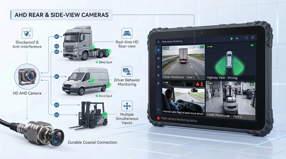
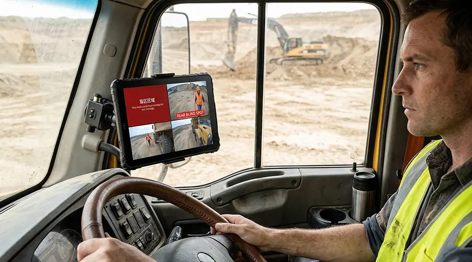
A multi-camera system becomes a safety system when the tablet knows which camera to display based on what the vehicle is doing. Reverse gear engages → rear camera fills the screen. Left turn signal → left side camera appears. Brake lights activate → rear camera with distance overlay. These automatic camera switches are driven by trigger signals from the vehicle's electrical system.
Common Trigger Signal Sources and Wiring Methods
GPIO configuration on the camera hub: Each trigger signal connects to a GPIO input on the tablet's camera hub or docking station. The GPIO inputs must be configured for the vehicle's voltage level — 12V for light-duty vehicles, 24V for heavy trucks and buses. Optically isolated GPIO inputs are strongly recommended: they prevent ground loops and protect the tablet from voltage spikes on the vehicle's lighting circuits. Tablets with CAN Bus and GPIO integration can read both digital trigger signals and vehicle speed data through a single dock connection.
Part 4: ADAS and DMS – When Cameras Become Safety Systems
ADAS (Advanced Driver Assistance Systems) and DMS (Driver Monitoring Systems) add a processing layer on top of the camera inputs. The cameras feed video to an AI processor — either on the tablet itself or on a dedicated ADAS module — that runs object detection, lane departure warning, and driver fatigue algorithms in real time. This changes the hardware requirements significantly.
Hardware Requirements for ADAS and DMS Processing
ADAS: Forward-Facing Intelligence
Forward-facing camera mounted behind the windshield. AI processor detects vehicles, pedestrians, lane markings, and traffic signs. Generates real-time alerts: forward collision warning, lane departure warning, pedestrian detection.
Requires dedicated AI processor — tablet CPU alone cannot run ADAS inference at vehicle speeds
Camera must be high dynamic range (HDR) to handle transition from shadow to direct sunlight
Mounting position is critical — must have unobstructed forward view through the windshield's swept area
DMS: Driver-Facing Monitoring
Infrared camera mounted on the dashboard or A-pillar, facing the driver. AI processor detects eye closure, head pose, yawning, and phone usage. Generates real-time alerts: fatigue warning, distraction warning, smoking detection.
Requires IR illuminator — works in complete darkness inside the cab
AI processing can run on the tablet if the SoC has a dedicated NPU (Neural Processing Unit)
Data privacy: DMS video should be processed locally — only alert events and metadata should be uploaded to the cloud
AI processing architecture decision: The AI inference can run on the tablet's SoC (if it has an NPU), on a dedicated ADAS module connected to the camera hub, or on a separate edge computing device. On-tablet processing is the simplest architecture but requires a tablet with sufficient compute headroom — the NPU must run continuously while also handling fleet applications. Dedicated ADAS modules offload AI processing entirely, keeping the tablet free for fleet management tasks. For fleet safety solutions that combine telematics with video, the hardware architecture must be designed for the specific AI workload, not retrofitted after deployment.
Part 5: Camera Installation and Cable Routing Best Practices
The best camera system fails if the cables are pinched in a door seal, the connectors corrode from road salt, or the camera bracket vibrates loose after 10,000 km. Installation quality determines system reliability more than any other factor.
Camera Installation Checklist
Cable routing: Run camera cables through existing grommets and wire looms wherever possible. Never route a cable through a door seal — the repeated compression will eventually cut through the insulation. For tractor-trailer combinations, use coiled cables or quick-disconnect connectors at the coupling point.
Connector weatherproofing: Apply dielectric grease to all BNC and power connectors before assembly. Wrap outdoor connections with self-amalgamating tape — it forms a waterproof seal that won't degrade with heat and vibration like electrical tape. This is especially critical for vehicle-mounted hardware exposed to road spray and weather.
Cable strain relief: Secure cables every 30 cm with cable ties or P-clips. Leave a small service loop at each connector to absorb vibration. A cable that's pulled tight will fatigue at the connector within months of vehicle operation.
Camera aiming and validation: After installation, view each camera feed on the tablet with the vehicle in its normal operating configuration — trailer attached, load on board, driver in seat. Adjust camera angle so the critical area (rear bumper, side blind spot, driver's face) is centered in the frame. Lock the camera bracket in place — if it can be adjusted by hand, it will move over time.
Frequently Asked Questions
Why choose AHD cameras over IP cameras for vehicle installations?
AHD cameras provide near-zero latency — critical for real-time maneuvering where a 300ms delay in the video feed can mean the difference between avoiding an obstacle and hitting it. The locking BNC connectors are vibration-resistant, and coaxial cable is inherently shielded against vehicle electrical noise. IP cameras introduce encoding delay and use non-locking RJ45 connectors that require additional strain relief for vehicle use.
How much storage do I need for 4-channel AHD recording?
At 1080p/25fps with H.264 compression, 4 channels generate approximately 108 GB per 10-hour driving shift. With a 1TB storage drive and loop recording, you can retain 8-9 days of footage before overwrite begins. Use industrial-grade storage rated for sustained write operations — consumer memory cards will fail within weeks under continuous 24 Mbps write loads.
How do I wire camera trigger signals from the vehicle?
Tap into the reverse light circuit, turn signal circuits, and brake light circuit at their respective locations. Use optically isolated GPIO inputs on the camera hub to prevent ground loops. Turn signals require a latching configuration — the camera view must stay active for several seconds after the last signal pulse. For speed-based camera switching, CAN Bus wheel-based speed is more reliable than GPS speed.
Does TOPICON support 4-channel AHD camera integration on fleet tablets?
Yes. TOPICON rugged MDTs support up to 4-channel 1080p AHD camera input via dedicated camera hub accessory, with GPIO trigger inputs for reverse, turn, and brake signal integration. ADAS and DMS processing is supported through dedicated AI modules or on-tablet NPU depending on the device model. Contact our integration engineering team for camera system specifications →
Planning a Multi-Camera Vehicle Safety System?
TOPICON rugged MDTs support 4-channel AHD camera input with trigger signal integration, ADAS/DMS processing, and industrial-grade storage for continuous multi-camera recording in fleet vehicles.
Related Integration & Safety Resources