Inland Waterway Navigation Tablet — Single Vessel Deployment & Fleet Scaling Notes
An independent inland waterway operator runs a cargo vessel on a navigable river system that crosses multiple network coverage zones. The navigation task requires continuous position fix — the navigable channel shifts with water level, bridges impose clearance limits, and lock passages demand accurate positioning relative to the lock wall. The problem was not the navigation software. The problem was the metal hull, the wheelhouse display under direct sunlight, and the power architecture of a 24V marine electrical system. This article documents the hardware configuration that resolved all three — and the engineering considerations for scaling the same architecture to a fleet.
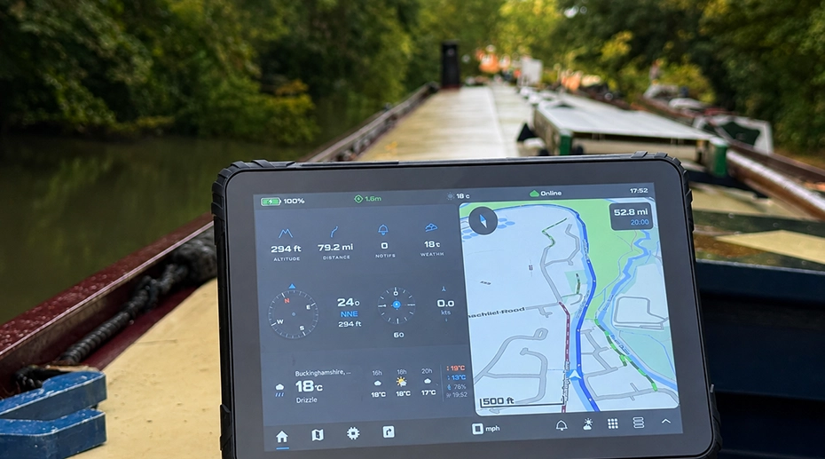
Table of Contents
1. The Operating Scenario
The vessel is an inland cargo barge operating on a navigable river system with a mix of open water sections, narrow canal segments, and lock passages. The wheelhouse carries a crew of two — a captain and a helmsman — and the vessel operates through the navigation season at 10 to 12 hours of daylight operation per day.
The navigation task is fundamentally different from road-based fleet navigation. There is no fixed road. The navigable channel shifts with water level. Bridges impose height and clearance limits. Lock schedules affect route timing. The navigation display must show depth contours, bridge clearances, and lock locations alongside the vessel's position — and the position must remain accurate enough to determine which side of a channel the vessel is on when two barges are meeting.
The operator had previously used a consumer-grade tablet mounted on a suction-cup bracket. The failure pattern was consistent: position drift in canal sections with tall embankments, complete signal loss during lock passages, and display washout during midday operation. Each failure required the helmsman to fall back to paper charts or slow the vessel until position was re-established. The operational cost was measurable — lock passage timing and canal speed restrictions had to be managed with an additional margin to account for navigation uncertainty.
2. The Metal Hull Problem
The primary GNSS failure was structural, not electronic. A steel-hulled vessel acts as a Faraday cage for the L-band satellite signals at approximately 1.5 GHz that GNSS receivers depend on. When a tablet with an internal antenna is mounted inside the wheelhouse, the surrounding steel attenuates the signal to the point where the receiver cannot maintain lock — even in open water with an unobstructed sky.
The failure is more severe in the wheelhouse than on the open deck. The wheelhouse is enclosed on all sides, often with additional steel structure in the roof for equipment mounting. The internal antenna of a consumer tablet sees only the signal that penetrates the enclosure — which in practice is close to zero. The previous tablet had been receiving intermittent signals only when the wheelhouse door was open.
The solution is an external GNSS antenna mounted on the wheelhouse roof or on a mast above the vessel's highest structure. The signal travels through a coaxial cable to the tablet's MMCX or SMA antenna port. The receiver stays inside the tablet — only the antenna is repositioned outside the signal-blocking enclosure. The GNSS hardware selection guide covers the antenna architecture options in detail.
3. Wheelhouse Display & Sunlight Readability
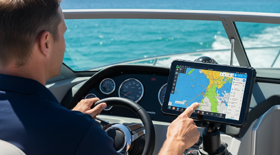
The wheelhouse of an inland vessel has a large forward window — essential for navigation but also a source of direct sunlight on the instrument panel from mid-morning to mid-afternoon. The previous tablet with a 400 to 500 nit display became unreadable during this period. The helmsman was forced to shield the screen with one hand while operating the vessel with the other, or rely on the chart plotter's hardcopy backup.
A 1000-nit display with anti-glare treatment and optical bonding addresses this. The brightness provides sufficient emission to compete with direct sunlight. The anti-glare coating diffuses the reflected sunlight across the screen surface instead of concentrating it into a visible reflection. Optical bonding eliminates the internal air gap between the display panel and the touch glass — removing two internal reflection surfaces that would otherwise reduce effective contrast.
The operator installed an optional sunshield cap on the tablet for additional protection against side-angle sun in the late afternoon. This was not strictly necessary given the 1000-nit panel with anti-glare, but the crew preferred it as a hardware-level guarantee against readability issues. The display comparison analysis covers the effective contrast calculation in more detail.
4. Marine Electrical Integration
The vessel electrical system operates at 24V DC nominal. Voltage on a marine system varies more widely than on a road vehicle — battery charging can push the system to 28V or higher, and heavy loads such as the bow thruster or winch can cause momentary voltage sag below 20V. A tablet powered through a standard 12V accessory socket or a USB adapter has no tolerance for this range.
The vehicle mount tablet platform with 9-36V wide input covers this voltage range natively. The device accepts the full marine system voltage directly without a converter. Ignition-sensing logic was not used in this deployment — vessels do not have an ignition key in the automotive sense — so the power input was wired to the wheelhouse distribution panel and the tablet remains powered while the vessel is operating.
For a marine deployment, the more relevant power consideration is surge protection. The bow thruster and anchor windlass draw several hundred amps when activated. This can induce voltage transients on the DC distribution system. The tablet's power input includes input filtering and surge protection that absorb these transients before they reach the device's internal power regulation. The DC-DC converter analysis covers the isolation architecture for vessels operating electrical systems with high inductive loads.
5. The Hardware Configuration
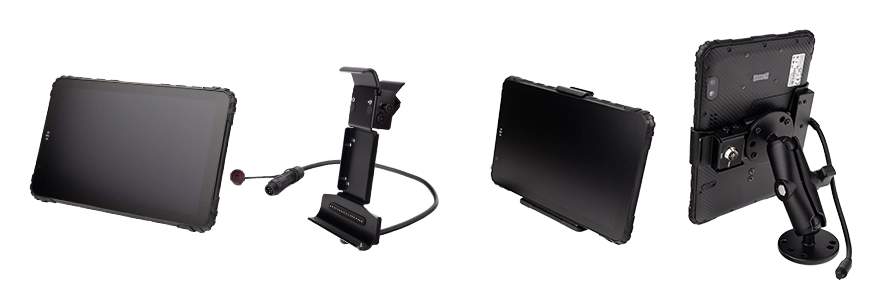
The vessel was equipped with the following configuration:
• GNSS: External MMCX antenna mounted on the wheelhouse roof, cable routed through a weather-sealed gland into the instrument panel
• Power: 9-36V DC wired to the wheelhouse distribution panel with fuse protection
• Mounting: RAM mount ball on the instrument panel, short arm to keep the screen at the helmsman's natural line of sight
• Docking: Quick-release dock for tablet removal during docked periods
• Software: Inland navigation application with offline chart packs and position tracking
The quick-release dock allows the tablet to be removed when the vessel is docked — for cleaning, storage, or hardware inspection during the off-season. The wheelhouse remains operational with the dock in place; only the tablet is removed. The in-vehicle tablet hardware overview covers the deployment flexibility this architecture provides.
6. Outcome & Fleet Scaling Considerations
The configuration change addressed the three failure modes identified in the previous deployment. The operational difference was observed across the first navigation season:
The previous configuration was a consumer tablet with an internal antenna, powered through a 12V accessory adapter, mounted on a suction-cup bracket. All three components failed in the marine environment. The IP67-sealed enclosure eliminated water ingress through the charging port. The 9-36V direct-wire input removed the accessory adapter that was the source of power interruptions. The RAM-mount dock eliminated the suction-cup bracket failures under wheelhouse vibration.
Extending this configuration to a fleet introduces additional considerations. A single vessel can be managed by physical access — the tablet is removed, updated, and re-docked when needed. A fleet operating multiple vessels requires a different management approach. Central firmware and configuration distribution becomes necessary when physical access to each vessel is not practical. The MDM platform for fleet device management covers the remote management layer that scales the single-vessel configuration to multi-vessel operation.
Single Point of Failure
A navigation tablet that loses position fix during a lock passage is a single point of failure that affects the vessel's entire operating schedule. The lock passage is a controlled sequence — the vessel must approach, hold position, wait for the lock to fill or empty, and exit before the next vessel enters from the opposite direction. If the helmsman cannot see the vessel's exact position relative to the lock wall, the approach speed drops, the entry margin increases, and the lock cycle takes longer than the schedule allows. Multiply this by every lock on the route and every vessel in a fleet, and the cumulative delay becomes the difference between meeting the operator's cargo delivery commitments and falling behind. The external antenna architecture that keeps position fix continuous through the lock passage is not a convenience feature — it is the operational basis of the schedule.
7. Frequently Asked Questions
Why does a metal-hulled vessel need an external GNSS antenna?
A steel hull acts as a Faraday cage for the L-band satellite signals that GNSS receivers depend on. When the tablet is inside the wheelhouse, the surrounding steel attenuates the signal to the point where the receiver cannot maintain lock. An external antenna mounted on the wheelhouse roof or a mast routes the signal through a coaxial cable to the tablet's antenna port. The GNSS hardware selection guide covers the antenna architecture options.
What display brightness is needed in a wheelhouse?
700 to 1000 nits with anti-glare treatment and optical bonding is the practical minimum for a wheelhouse with large forward windows and direct sunlight. Below 700 nits without anti-glare, the display becomes unreadable during the midday period when the sun angle is most direct. An optional sunshield can supplement the display for late afternoon side-angle sun. The display brightness comparison covers the effective contrast calculation.
How does marine electrical voltage differ from vehicle voltage?
A marine 24V system is nominal — actual voltage ranges from approximately 20V under heavy load to 28V during battery charging. Heavy inductive loads such as bow thrusters and winches can cause momentary voltage sag below the nominal range. A tablet with 9-36V wide input and input filtering accepts the full marine voltage range directly without a converter. The DC-DC converter analysis covers the isolation architecture for high-inductive-load systems.
What changes when extending this configuration to a fleet?
The hardware configuration remains the same per vessel — the tablet, antenna, power wiring, and mount. What changes is the management layer. Physical access to update firmware or change configuration on a single vessel is practical. On a fleet, remote management becomes necessary. The MDM platform for fleet device management provides OTA firmware updates, configuration distribution, and device monitoring that scale the single-vessel setup to multi-vessel operation.
Equipping an Inland Vessel or Planning Fleet Rollout?
The metal hull, wheelhouse environment, and marine power architecture determine the hardware configuration. Request a hardware evaluation kit or discuss the specific requirements for your vessel class and route.