Off-Grid Search & Rescue Navigation — MDT880 Multi-Vehicle Case Study
A regional search and rescue organisation operates three vehicle types across a 900-square-kilometre mountainous area — UTVs for trail access, 4x4 rescue trucks for road-accessible zones, and light forest patrol vehicles for routine monitoring. Most of the operating area has no cellular coverage. The team needed navigation that works without a network, and coordination that keeps every vehicle visible to the incident commander. This deployment note covers the hardware configuration and the two software integration paths that made it work.
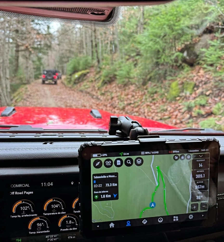
Table of Contents
1. The Operating Environment
The organisation responds to missing hiker calls, medical evacuations from remote trailheads, and wildfire monitoring. The operating area ranges from 200 metres above sea level at the valley floor to 2,400 metres at the ridge lines. Terrain includes forestry roads that are passable only to UTVs, fire trails that require 4x4 vehicles with high clearance, and mountain footpaths that are accessed on foot after the vehicle reaches a trailhead.
Cellular coverage exists near the valley towns and along the main highway. Once a vehicle turns onto a forestry road, the signal drops within the first kilometre and does not return until the vehicle descends. Radio coverage from the repeater network covers approximately 60% of the operating area — the remaining 40% is in terrain shadows where VHF does not reach. The team has two portable satellite phones for emergency communication, but they are not used for routine coordination because of cost and limited bandwidth.
Before the tablet deployment, navigation was done with paper topographic maps and handheld GPS units. The incident commander tracked vehicle positions by radio check-in — each vehicle reported its grid reference every 30 minutes. This gave the commander a position update that was up to 30 minutes old. In a moving search that covers several kilometres, the reported position and the actual position could be far apart. The public safety hardware solutions overview covers the broader deployment context for emergency response fleets.
2. Where Standard Navigation Failed
The first failure was the type of map. Consumer navigation applications focus on road networks. In a forest, the road network ends at the forestry road, and the search area is off-road. The team needs to see terrain features — ridgelines, drainage channels, slope angle, contour lines — to plan a search pattern and predict where a missing person might have walked. A consumer map that shows an empty green area where the search is happening is not usable for the task.
The second failure was the dependency on connectivity. Some mapping applications will not display maps without downloading them first, and some will not display at all without a network connection for tile requests. In the areas where the team operates, the last cellular signal is at the trailhead. Beyond that point, the navigation device must function entirely offline. The GNSS hardware selection guide covers the positioning architecture for off-grid operations.
The third failure was team visibility. Each vehicle was navigating independently on its own GPS unit. The commander could not see where the other vehicles were on a shared map. In a coordinated search, if one vehicle finds the subject, the commander needs to know the closest support vehicle and its route to the discovery point. Without a shared map, this calculation was done over voice radio with grid references that had to be plotted by hand on a paper map at the command post.
3. Hardware Configuration Across Three Vehicle Types
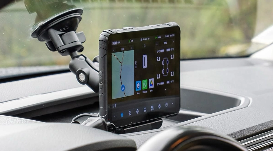
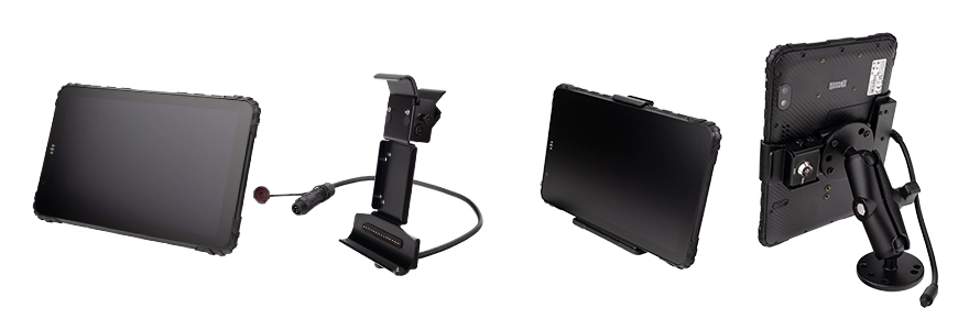
The organisation standardised on one tablet platform across all three vehicle types. The configuration was adapted to the electrical and mounting characteristics of each vehicle class:
The tablet carries an integrated multi-constellation GNSS receiver. For UTVs operating under tree canopy on forestry roads, an external antenna was added — the open-cab mounting position places the internal antenna under the vehicle body, where satellite signals are attenuated. The external antenna is mounted on the roll cage above the roofline. The vehicle mount tablet platform with external antenna support covers the antenna architecture.
4. Offline Terrain Navigation
The system integrator built a customised version of an open-source offline navigation platform. The application loads three data layers that are stored entirely on the tablet's internal storage — no network requests, no cached tiles:
The first layer is a digital elevation model (DEM) at 10-metre resolution covering the full operating area. The DEM provides the underlying terrain shape, which the application uses to render a hillshade — a shaded representation of the terrain that makes ridgelines and valleys visible without contour lines. The second layer is the contour line overlay at 20-metre vertical intervals. The third layer is a trail network dataset with trailhead locations, fire roads, and water sources, compiled by the organisation from local survey data and updated annually.
The heat map function is generated at runtime. The application records the ground track of every vehicle in the fleet, and renders the accumulated track density as a colour overlay on the map. Over weeks of patrol operations, the heat map shows which trails are used most frequently, which drainages have no recorded coverage, and which areas have never been surveyed. For search planning, the incident commander can overlay the heat map with a search grid and prioritise areas where a missing person might have taken an established path.
All layers are stored on the tablet. The navigation functions — position display, track recording, route calculation, contour rendering — operate without any network connection. The in-vehicle computing platform provides the storage and processing for the full map dataset without needing an external storage device.
5. Team Tracking Without a Network
The team tracking function does not use cellular data. It uses a LoRa radio module connected to the tablet through the expansion interface, with a whip antenna mounted on the vehicle roof. LoRa operates in the license-free ISM band and achieves range of several kilometres in open terrain and up to a kilometre in dense forest, depending on the specific module and antenna configuration.
Each vehicle broadcasts a position packet at 30-second intervals — vehicle identifier, coordinates, heading, and speed. The packet is small, and the LoRa network does not require any infrastructure. Any vehicle within range of another receives the packet. The application displays the position of every vehicle in the mesh on the shared map. The incident commander, riding in one of the vehicles, sees the same map as every other vehicle in the fleet.
For larger search operations that extend beyond LoRa range, the command vehicle carries a portable satellite data terminal. Position data from the mesh is forwarded through the satellite link at a configurable interval — typically every 5 minutes rather than every 30 seconds — to reduce airtime cost. The satellite link extends the command network to distant vehicles without altering the local LoRa mesh.
The LoRa module is an expansion interface option. The SI integrated it with the application through the platform's Android SDK, which exposes the expansion interface as a serial data channel. The navigation hardware architecture guide covers the SDK integration approach for system integrators building custom navigation applications.
6. Outcome After Deployment
The tablets were deployed across the full vehicle fleet. The most significant operational change was the elimination of the 30-minute radio check-in cycle. Vehicle positions update continuously on the shared map, and the incident commander can see the relative position of every vehicle in the search area without asking for a grid reference.
The second change was search pattern planning. The heat map and the DEM contour layers give the commander the terrain context to plan a search grid that follows the ridgelines rather than crossing them repeatedly. Teams on different vehicles can be assigned different drainages and maintain separation without repeated radio coordination. The navigation application displays the search grid overlay on the contour map, so every vehicle in the search sees the assigned sector boundary.
The third change was incident documentation. Every vehicle's track is recorded on the tablet and uploaded to the command post when the vehicle returns to cellular coverage. The recorded tracks show exactly which terrain was covered by which vehicle at what time. This documentation supports after-action review and, in the case of a missing-person search, provides the record required for reporting to the regional emergency coordination authority.
Single Point of Failure
A navigation tablet that loses position fix in off-grid terrain is a single point of failure that affects not just the vehicle it is installed in, but the entire team coordination picture. The LoRa mesh depends on each vehicle broadcasting its position. A vehicle that cannot determine its own position cannot broadcast it. The commander's map shows a gap where that vehicle should be. In a search grid where each vehicle is assigned a separate sector, a gap in the map is not a technical inconvenience — it is a gap in the search coverage. The hardware configuration — external GNSS antenna for canopy environments, offline DEM and contour storage, LoRa expansion interface — is what prevents the navigation system from becoming the limitation on the search operation itself.
7. Frequently Asked Questions
How does the navigation system work without cellular coverage?
All map data — the digital elevation model, contour lines, and trail network — is stored on the tablet's internal storage. The application reads these layers locally without making any network requests. The GNSS receiver determines position directly from satellite signals, which are available anywhere with a view of the sky. The tablet does not need a cellular connection to display position, terrain, or the recorded track.
What is the range of the LoRa team tracking?
LoRa range depends on terrain and antenna placement. In open terrain with line of sight, several kilometres are achievable. In dense forest with terrain between vehicles, the effective range may be under a kilometre. The mesh architecture allows vehicles to relay packets through other vehicles in the network, which extends the total coverage compared to direct vehicle-to-vehicle communication. For operations that exceed the LoRa range, a satellite data terminal in the command vehicle forwards position updates at a reduced interval.
Why is an external GNSS antenna needed on the UTV?
An open-cab UTV typically has a metal or composite roof structure above the dashboard, and the vehicle body itself is between the internal antenna and the sky when the tablet is mounted at dashboard level. In forested terrain, tree canopy attenuates satellite signals further. An external antenna mounted on the roll cage above the roofline has a clear view of the sky and receives stronger signals than an internal antenna in the same vehicle. The vehicle mount tablet platform supports external antenna configurations across the model range.
Can the same tablet platform run on all three vehicle types?
Yes. The tablet platform is common across the three vehicle types. The differences are in the power wiring, the mounting bracket, and the antenna configuration, which are adapted to each vehicle's electrical system and mounting structure. Standardising on one tablet model simplifies the fleet's spare parts inventory, MDM enrolment, and application update process. The in-vehicle tablet hardware overview covers the platform architecture.
Equipping Off-Grid Response or Patrol Fleets?
The antenna configuration, offline map storage, and expansion interface determine whether the navigation system works in terrain without cellular coverage. Request a hardware evaluation kit or discuss the integration architecture for your fleet.