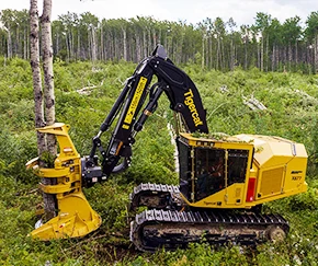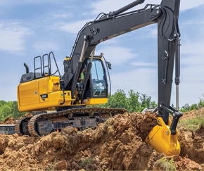
Mining Fleet GNSS — Metal Cab Signal Loss and External Antenna Deployment
A mining operator running haul trucks and excavators across an open pit lost GNSS position fix whenever the equipment was inside the cab with the doors closed. The fleet management system showed the equipment parked at the maintenance yard even when it was at the loading face. The dispatch team could not route the trucks reliably. This deployment note covers why the metal cabin blocked the signal, what external antenna configuration restored continuous tracking, and how the same antenna architecture handled both haul trucks and excavators.

Table of Contents
1. The Operation
The mine operates a mixed fleet of haul trucks, hydraulic excavators, and front-end loaders across a 4-square-kilometre open pit and the surrounding haul roads. Operations run 24 hours in two shifts. The fleet management system tracks every piece of equipment and assigns haul cycles in real time. A truck that is not visible to the system cannot be dispatched efficiently — the dispatch operator must rely on radio calls and manual position updates.
The operational goal is continuous tracking of every vehicle: position, speed, heading, and load status. The position data feeds into the dispatch algorithm, which assigns the nearest available truck to each loading cycle. When a truck's position is stale, the dispatch algorithm cannot place it correctly. The operational cost is not measured in the tracking system itself — it is measured in idle truck time at the loading face and in haul cycle inefficiency.
2. Why the Metal Cab Blocks GNSS
A haul truck cab and an excavator cab are both steel structures with reinforced frames. The cabin walls, roof, and floor form a conductive enclosure around the operator and the mounted equipment. At GNSS frequencies — 1575.42 MHz for GPS L1, 1176.45 MHz for L5 — the steel acts as a partial Faraday cage. Signals from satellites above the vehicle do not pass through the roof to reach an internal antenna.
The attenuation depends on the thickness and continuity of the steel. A road vehicle cab has thinner panels and glass windows that partially transmit GNSS signals. A mining equipment cab has thicker steel, smaller windows, and often additional reinforcement for the ROPS structure. The signal attenuation through this structure is significant enough that the internal antenna receives little or no usable signal.
The failure appears as a lost position fix. The tablet's GNSS receiver cannot compute a position without at least four satellites with adequate signal strength. Inside the metal cab, the number of satellites visible to the internal antenna drops below four, and the receiver stops reporting position. The tracking system sees the last known position before the cab door closed and holds it as the current position — or flags the vehicle as offline. A GPS signal loss diagnosis guide for fleet tablets covers the receiver-level troubleshooting path.
3. The Open Pit Adds a Second Problem
A metal cab is the first problem. The open pit is the second. At the bottom of the pit, the walls block a significant portion of the sky. The GNSS receiver needs line-of-sight to satellites above the horizon. In a deep pit, the visible sky is reduced to the cone of angles above the pit rim. Satellites at low elevation angles — which are often the ones that provide the strongest signal in open terrain — are blocked by the pit wall.
This reduces the number of satellites the receiver can use. A device that tracks only GPS may see four or five satellites at the pit bottom instead of the eight or ten available at the surface. Four satellites is the minimum for a position fix. Any drop below four — caused by a momentary obstruction or signal reflection — interrupts the fix.
Multi-constellation reception addresses this. A receiver tracking GPS, GLONASS, Galileo, and BeiDou has access to over 100 satellites. At the pit bottom, even with the reduced sky view, the receiver can still see 15 to 20 satellites across four constellations. The position fix remains continuous. The GNSS hardware selection guide covers the constellation coverage requirements for mining operations.
4. Antenna Configuration
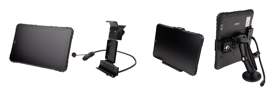
The deployment uses an external GNSS antenna mounted outside the cab on each piece of equipment. The signal travels from the antenna through a coaxial cable into the tablet's MMCX antenna port. The tablet's internal receiver processes the signal as if it came from an internal antenna, but the signal path begins outside the metal enclosure.
• Antenna: EXT-GPS-01 external GPS antenna with L-shaped cable, mounted on a bracket above the cab roofline
• Adapter: EXT-GPS-02 conversion cable (MMCX to SMA female) — connects the antenna cable to the tablet's MMCX antenna port
• Cable routing: Coaxial cable routed from the antenna to the cab interior, with a weather-sealed gland at the entry point
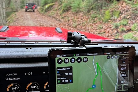
• Mounting: RAM mount ball on the operator console with a short arm, positioning the screen in the operator's forward line of sight
• Power: Direct wire to the 24V equipment electrical system with inline fuse and ignition sensing
• Connectivity: 4G LTE for position reporting to the dispatch system
Three Antenna Options for Different Deployment Scenarios
For the mining deployment described here, the EXT-GPS-01 with EXT-GPS-02 adapter was selected because it provides a permanent, weather-sealed antenna installation that can be inspected during scheduled maintenance without disturbing the tablet's docking position. The EXT-GPS-03 USB GPS receiver is an alternative for retrofit scenarios where routing a coaxial cable is impractical — the entire GNSS module moves outside the cab and connects through the tablet's USB-A port. It is useful when the equipment was not designed for a permanent antenna cable, but the trade-off is that the receiver module itself becomes an additional component to mount and protect on the equipment exterior.
The antenna mounting position is critical. The antenna must have an unobstructed view of the sky — not shielded by the cab roof, the exhaust stack, or any other structure. On a haul truck, the antenna is typically mounted on a bracket attached to the cab roof or to a dedicated antenna mast. On an excavator, the antenna is mounted on the highest point of the cab structure with a clear view above the machine's boom. The vehicle mount tablet platform with external antenna support covers the antenna architecture across the model range.
External GPS Antenna Installation
Demonstration of the external GNSS antenna connection on the MDT865. The EXT-GPS-01 antenna routes the satellite signal from a roof-mounted position to the receiver inside the cab — the configuration required for metal-bodied mining equipment where the internal antenna cannot reach the sky.
5. Haul Trucks vs Excavators
The two equipment types present different deployment challenges, even though the antenna architecture is the same.
Haul trucks move continuously between the loading face and the dump point. The vibration profile is dominated by engine and drivetrain vibration at low frequencies, with periodic impact events when the truck crosses haul road joints or dumps a load. The tablet mounting must withstand this environment without loosening. The antenna cable must be routed away from the engine compartment and any high-current cables to avoid electromagnetic interference.
Excavators operate in a stationary position for extended periods. The vibration profile is dominated by the hydraulic system — the pump motor and the slew motor create higher-frequency vibration than the haul truck drivetrain. The cab rotates with the machine, so the antenna on the cab roof maintains its sky view throughout the swing cycle. The specific challenge for excavators is the hydraulic pump EMI, which can disrupt the touchscreen and the GNSS receiver if the tablet and antenna cable are not routed away from the pump housing. The mining vehicle computer deployment guide covers the equipment-specific engineering considerations.
6. Outcome
The deployment was completed across the fleet. The most direct change was position fix continuity. Vehicles that previously showed as offline when inside the cab now report position continuously. The dispatch algorithm has accurate positions for every truck, and the dispatch operator no longer relies on radio calls to locate equipment.
The second change was in the pit. Multi-constellation reception maintained position fix at the pit bottom where single-constellation receivers had lost it. The dispatch system now tracks trucks through the full haul cycle — from the surface, down the ramp, at the loading face, and back up.
The third change was reduced maintenance on the tracking hardware. The previous consumer tablets were replaced an average of once per year due to vibration damage or screen failure. The vehicle-grade tablets with RAM mount and key-lock dock have continued operating without replacement. The EXT-GPS-01 antenna and EXT-GPS-02 adapter cable require periodic inspection — the connections are checked during scheduled equipment maintenance to verify that both the antenna-side and tablet-side connectors are fully seated and the cable jacket is intact.
Single Point of Failure
The MMCX connector on the EXT-GPS-02 adapter is a single point of failure that the tracking system reports as "no signal." The dispatch operator sees a truck that has stopped reporting. The assumption is that the truck has entered a coverage shadow, is parked, or has an equipment fault. The actual cause is an MMCX connector that has worked loose over months of vibration and temperature cycling. The truck continues to operate — but the dispatch system cannot see it. In mining operations, where haul cycle timing determines the mine's throughput, the loss of visibility on a single truck costs more than the hardware itself. The external antenna architecture restores the sky view, but the MMCX mechanical interface is the component that requires periodic inspection to remain reliable.
7. Frequently Asked Questions
Why does the GNSS signal drop inside a mining equipment cab?
A mining cab is a steel structure with reinforced frames and heavy panels. At GNSS frequencies around 1.5 GHz, the steel acts as a partial Faraday cage. The satellite signals above the vehicle do not pass through the roof to reach an internal antenna. The number of visible satellites drops below the minimum for a position fix, and the receiver stops reporting.
What antenna position is required on mining equipment?
The antenna must have an unobstructed view of the sky. On a haul truck, this is typically the cab roof or a dedicated antenna mast above the cab. On an excavator, the highest point of the cab structure with a clear view above the boom. The antenna should not be shielded by the exhaust stack, the ROPS structure, or any other equipment mounted above the cab.
Does multi-constellation GNSS help in an open pit?
Yes. At the bottom of an open pit, the pit walls block satellites at low elevation angles. A receiver tracking only GPS may see four or five satellites at the pit bottom. A receiver tracking GPS, GLONASS, Galileo, and BeiDou has access to over 100 satellites and can maintain a position fix with 15 to 20 visible satellites even in the reduced sky view of the pit.
How does the antenna cable survive the mining environment?
The coaxial cable is routed with protection against abrasion, heat, and vibration. Cable ties and conduit protect the cable run from the antenna down to the cab entry point. Two connections require attention during scheduled maintenance: the antenna-to-cable connection at the EXT-GPS-01 antenna body, and the EXT-GPS-02 MMCX adapter at the tablet's antenna port. Both must be verified as fully seated. A loose connection at either point presents the same symptom as a blocked antenna — loss of position fix. The GPS signal loss diagnosis guide covers the troubleshooting sequence.
Deploying GNSS Tracking Across a Mining Fleet?
The antenna mounting, constellation coverage, and cable routing determine whether the dispatch system maintains visibility on every truck and excavator. Request a hardware evaluation kit or discuss the configuration for your equipment class.